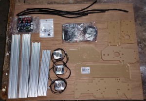
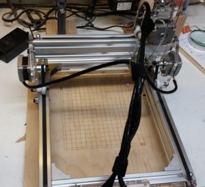
While setting up my NEJE 500mw Desktop violet laser engraver, I found there was absolutely no documentation. It came with a version of grbl on it, but I updated it to the latest Grbl 0.9j.
These settings are working pretty well for me. I’ve tweaked the dir port invert mask to make the origin (0,0) take place when the gantry is closes to the circuit board.
Grbl 0.9j ['$' for help]
>>> $$
$0=100 (step pulse, usec)
$1=25 (step idle delay, msec)
$2=0 (step port invert mask:00000000)
$3=2 (dir port invert mask:00000010)
$4=0 (step enable invert, bool)
$5=0 (limit pins invert, bool)
$6=0 (probe pin invert, bool)
$10=3 (status report mask:00000011)
$11=0.010 (junction deviation, mm)
$12=0.002 (arc tolerance, mm)
$13=0 (report inches, bool)
$20=0 (soft limits, bool)
$21=0 (hard limits, bool)
$22=0 (homing cycle, bool)
$23=0 (homing dir invert mask:00000000)
$24=250.000 (homing feed, mm/min)
$25=250.000 (homing seek, mm/min)
$26=250 (homing debounce, msec)
$27=10.000 (homing pull-off, mm)
$100=80.000 (x, step/mm)
$101=80.000 (y, step/mm)
$102=80.000 (z, step/mm)
$110=750.000 (x max rate, mm/min)
$111=750.000 (y max rate, mm/min)
$112=500.000 (z max rate, mm/min)
$120=1000.000 (x accel, mm/sec^2)
$121=1000.000 (y accel, mm/sec^2)
$122=10.000 (z accel, mm/sec^2)
$130=175.000 (x max travel, mm)
$131=1200.000 (y max travel, mm)
$132=175.000 (z max travel, mm)
ok


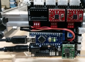
 Ok, Maybe one complaint. At some point during the first day, the laser quit being able to shut off during use. It appears that the SMD mount transistor on the board that controls the laser went bad. In my attempt to replace it, I managed to screw up the board a bit, but finally just soldered some jumper wires in place and plugged in a replacement transistor I had laying around. Bada Bing, Bada boom, I’m back in business. It looks a little goofy, but it works fine now.